

Get quote
Get Free Consultation!
We are ready to answer right now! free consultation.
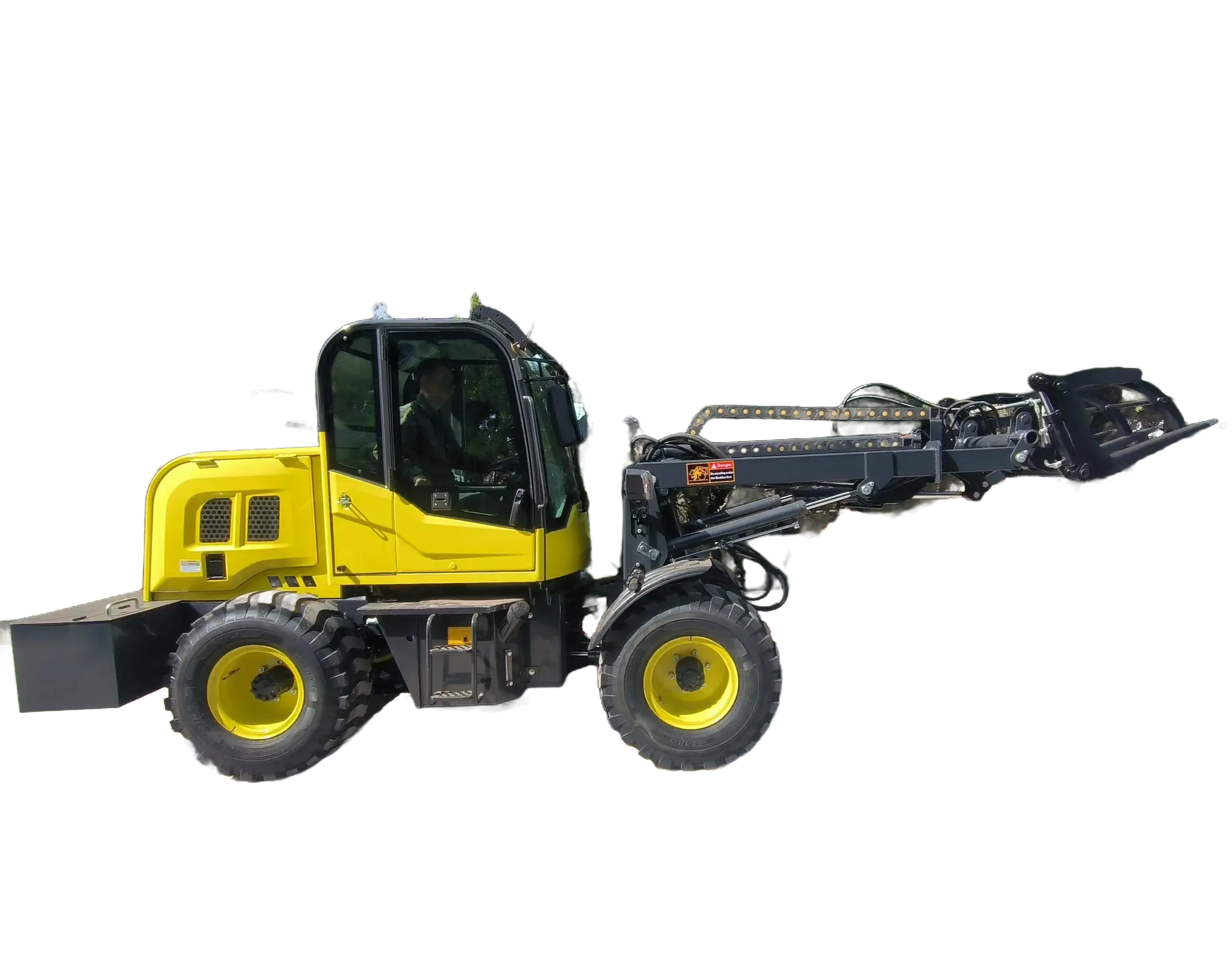
A buyer sees a telescopic boom clear a high truck and assumes the loader can carry its full rated load at that position. That assumption fails because reach changes leverage and stability. A telescopic wheel loader manufacturer should publish or supply capacity at the actual extension, attachment and boom position—not just maximum lift height.
MEGA’s telescopic loader range includes EC430 and TL16. EC430 publishes 800 kg on the main arm but 450 kg with the small arm extended. TL16 publishes 1,000 kg without extending and 600 kg with the arm fully extended. Those reductions are the central selection fact. Farms and yards should trace the load from ground pickup to discharge before choosing between them or a fixed-boom wheel loader.
A farm loading a high-sided receiver may need the extra height but carry only a modest load at full reach. A yard may appreciate forward reach that keeps the loader away from a truck, yet uneven ground and side articulation can reduce the operating margin. The final route must use manufacturer-approved load information and site controls.
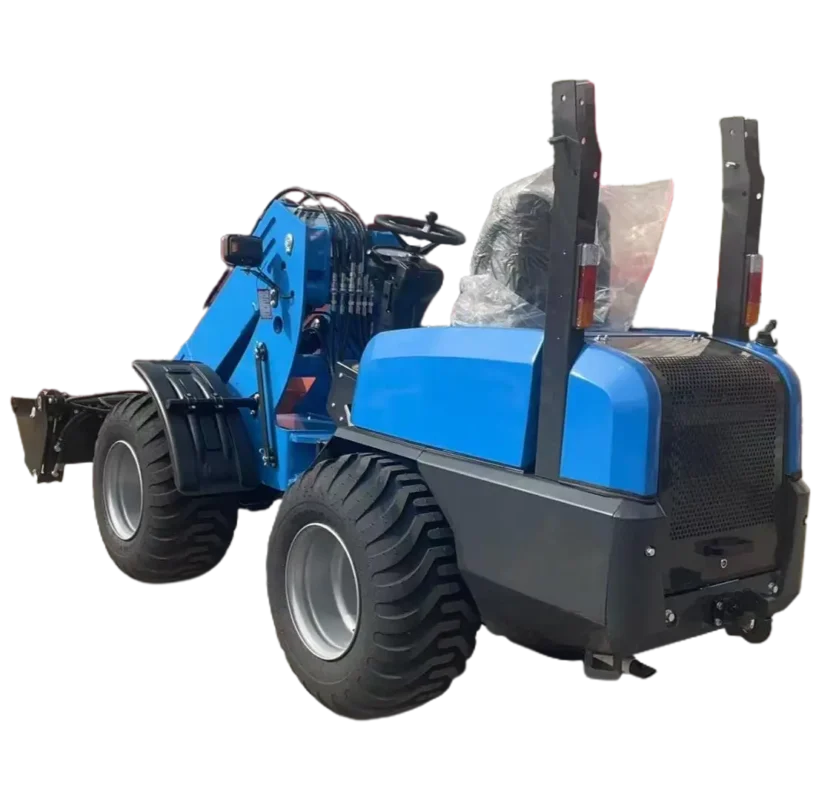
Divide the work into pickup, rollback, loaded travel, approach, boom raise, extension, discharge and return. For each stage, record load, attachment, boom position, steering angle and ground. The most restrictive stage sets the usable route.
The EC430 page lists an 800 kg maximum load on the main arm and 450 kg with the small arm extended. Its unloading height increases from 2,215 mm before extension to 2,825 mm after extension. Safe unloading distance rises from 830 mm to 1,350 mm after extension.
That geometry can help a compact farm loader reach into a receiver without driving against its side. It also means a 700 kg pallet that is acceptable near the main arm cannot simply be pushed outward. The buyer needs the load information for the exact attachment and extension, and the operator needs a visible boundary.
EC430 lists a 45-degree articulated turning angle, 1,800 kg vehicle-body weight, 242 mm ground clearance and 1,046 mm total wheel width. Its narrow form may suit restricted yards, but articulation while raised or extended must follow the manufacturer’s instructions. Narrow access does not create stability.
The TL16 publishes 1,000 kg without arm extension and 600 kg with the arm fully extended. Its 0.3 m³ bucket is 1,600 mm wide. The page lists 2,700-3,900 mm bucket dumping height, 5,096 x 1,500 x 1,700 mm dimensions and 2,666 mm minimum turning radius.
This model can address a higher receiver than EC430 on published figures, subject to identifying the selected boom position behind the height range. The buyer should not assume 600 kg applies at every combination of height, forward reach and articulation. Request the current load chart or approved capacity information and retain it with the machine.
TL16 also lists a 37 kW naturally aspirated engine, 16 MPa hydraulic system pressure, 280 mm ground clearance and oil service brake. These values help define the ordered machine but do not replace the boom-position limit.
Maximum height is useful only if the loader also reaches far enough and retains capacity. Measure the receiver lip, wall thickness, required discharge point and any guard rail. Then measure the approach surface and distance the loader can safely maintain from the edge.
If a wagon side is 2,200 mm high but the desired discharge point sits 900 mm beyond it, EC430’s before-extension unloading height may appear close while its published 830 mm safe distance may be insufficient. Extending raises height to 2,825 mm and distance to 1,350 mm, but the maximum load changes to 450 kg. The buyer must decide whether a smaller bucket or different cycle is acceptable.
For light feed, volume can fill a bucket before mass reaches the limit. Ask the manufacturer to approve the attachment and volume at extension. For dense material, a much smaller volume may reach 450 kg. One bucket choice should not be assumed safe for both.
TL16’s published dumping-height range of 2,700-3,900 mm needs a selected configuration and dimensional drawing. Identify the bucket position that produces each height, the associated forward reach and permissible load. If the truck varies across the fleet, measure the tallest critical side and the lowest overhead obstruction on approach.
Do not create a ramp merely to make an undersized loader clear a truck without engineering the ramp, edge protection and traffic route. Changing the receiving arrangement may be valid, but it becomes part of the project design.
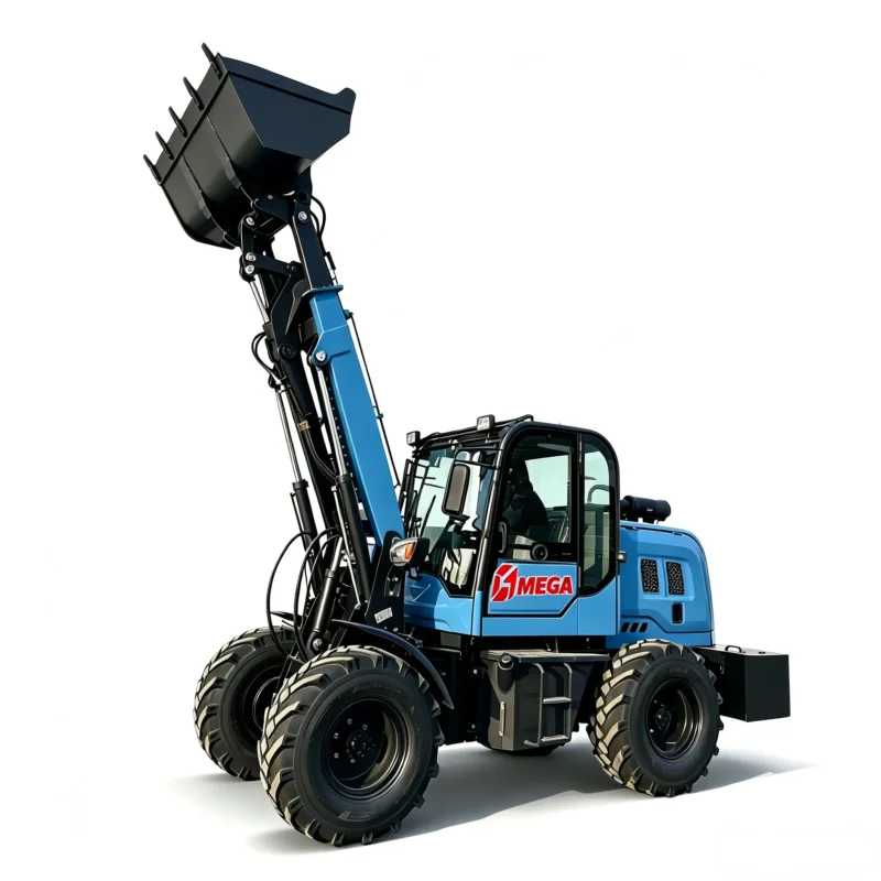
A telescopic boom moves the load centre forward. Soft soil, slope, potholes and side articulation can further alter the stability margin. Before operating at reach, prepare a level, firm loading zone that matches the manufacturer’s instructions and keeps other traffic away.
The farm may use the loader throughout a muddy yard, yet full-reach discharge should occur at a controlled position. Mark the wheel locations, remove loose material and confirm drainage. If the loader must articulate to align with the receiver, ask the manufacturer whether the published capacity applies in that position.
Travel with the boom and load in the approved low position. Extension is for the final controlled part of the cycle, not for carrying material across uneven ground. Where visibility is restricted, use site procedures and trained assistance consistent with local requirements.
Forward reach can keep the front axle away from a trench, hopper wall or truck, but only a site engineer or responsible person should set the safe edge distance. Do not use the boom to compensate for parking on an unstable shoulder. The loader’s stated safe unloading distance describes geometry, not the strength of the ground.
The dimensional pages for the Wacker Neuson 8095T and John Deere 326 P-Tier illustrate how manufacturers connect dimensions and working positions. Their capacities and configurations apply only to their own machines. Use the presentation logic to request complete MEGA data.
If the receiver is low enough and the route does not require forward reach, a standard loader can avoid the capacity reduction associated with extension. The MG936 lists a 2,000 kg rated load, 1.2 m³ bucket, 3,500 mm dumping height and 1,000 mm reach. It is much larger than EC430, so access and operating weight must also fit.
An aggregate yard with wide access and frequent 1-ton-plus buckets may be better served by MG936 than by stretching TL16 beyond its full-extension 600 kg limit. Compare material density, truck side, travel width, turning space and ground. The heavier loader should not be proposed when a low roof or narrow gate excludes it.
EC430’s 1,046 mm wheel width and 1,350 mm extended safe unloading distance can solve a narrow, modest-load route. If the job remains within 450 kg at extension and 800 kg on the main arm, its compact geometry may be more valuable than a larger bucket. The buyer should preserve those two load boundaries in training.
The commercial schedule should not contain one capacity cell. It should list the approved load without extension, at the buyer’s normal reach and at the maximum planned reach, each with the named attachment and boom position. Where only endpoint values are published, ask for the intermediate information needed by the job.
For TL16’s 0.3 m³ bucket, estimate load from the actual loose density and fill factor. Light feed may remain below 600 kg at full extension, while dense wet aggregate can reach the limit in a partly filled bucket. The supplier should approve the bucket and material route rather than treating volume as mass.
For EC430, identify whether the 450 kg extended limit includes the ordered bucket and coupler in the way the manufacturer defines capacity. Preserve that definition in the handover. An operator should not have to guess whether a loose attachment has already consumed part of the available load.
If the buyer adds forks, supply the pallet weight, dimensions and centre of gravity. The load moves farther forward as fork length, carriage and boom extension are combined. Ask for manufacturer-approved capacity at that geometry. A retracted 800 or 1,000 kg value cannot be transferred to long pallets at full reach.
This is also the point to decide whether an all-terrain forklift is a better route for repeated pallet stacking. Telescopic versatility does not remove the need for machine-specific load information.
The order should identify the exact attachment, maximum load at relevant boom positions, dumping height, forward reach, width, tires, engine, brakes and destination requirements. TL16’s page notes that parameters may change with design improvement, so request a current approved specification before production.
Record model and attachment identity. Under the manufacturer’s safe procedure, test steering, braking, boom raise, extension, rollback and discharge with a defined approved load. Show the boom position and ground. Avoid demonstrations that combine maximum load, maximum extension and sharp articulation without documented approval.
Inspect transit condition, boom sections, pins, hoses, tires, bucket and loose attachments. Confirm the load information and safety markings are present and match the ordered configuration. Operators should be trained to distinguish retracted and extended limits before the first production cycle.
The correct telescopic loader is not the machine with the tallest image. It is the one that retains enough approved load at the exact reach, remains stable on the prepared approach, and fits the route with useful clearance. EC430 and TL16 make different compromises; the buyer’s measured load path should decide between them.
After commissioning, mark the approved loading position at the receiver and keep the boom-position limits with the machine. If the site changes the bin, attachment or approach, repeat the review. A route that was safe at 830 mm forward distance may not remain valid when the receiver is moved or the ground settles.
Include a simple load record for unusual lifts: object mass, attachment, boom position, ground and authorisation. This does not replace the manufacturer’s load information. It prevents a one-off successful lift from becoming an undocumented routine. If the proposed object lies outside the approved chart or the operator cannot confirm its mass, use a different handling plan.
Review the loading pad after rain, settlement or resurfacing. A small tilt at the wheels can become more significant at an extended bucket. Keep drainage functional, prevent stockpiles from forcing an angled approach and restore the marked stand-off position when site traffic moves barriers.
Any replacement bucket or fork should trigger the same capacity and reach review before field use begins.
For pallet work where a mast truck may be more appropriate, compare the rough-terrain forklift load-centre method.
